Harry Hopkins/OBERPFAFFENHOFEN

SINCE IT FIRST ENTERED service, the Dornier 328 high-speed turboprop has been the subject of a great many detail refinements, not least to its aerodynamics, its propellers and systems. So extensive are these changes that the designation of the current production version has been changed from that of 320-100 to 328-110, and all the early -100s in service are being uprated progressively to the new standard.

The time it has taken to arrive at this definitive specification partly explains why it has taken so long for a test aircraft to be made available. Flight International has been able to put the aircraft through its paces, some four years after its roll-out.

The Dornier 328 is unusual as a high-speed turboprop in having been designed as a stand-alone product: others, such as the Saab 2000 and de Havilland Canada Dash 8-200, are basically derivatives of earlier, slower, machines. This shows in the long sleek fuselage-to-wing fairing, shaped for high speed, yet the high-aspect-ratio wing is nearly straight. This "TNT" (Tragflache Neue Technologie) wing has the same laminar-flow, rear-loaded profile, as that of the Dornier 228, but the aircraft is larger. The profile delivers low drag at high air speed and high lift at low air speed.

A walk-around shows up many of the latest differences: a new 3.6m-diameter (760mm larger than before) Hartzell six-bladed, carbonfibre-composite propeller; new ventral strakes; a dorsal extension ahead of the fin (which gives a Vmca of 8kt less than before, and a Vmcg better by more than 10kt); and de-icing of the stabiliser-to-fin area.

Not visible, but just as important, is a 32¡ landing-flap setting. The main undercarriage-fairings also house batteries and oxygen on each side, accessed through large doors. To save weight, the tail cone is made of composite (instead of titanium) when a customer (50% so far) chooses not to fit an auxiliary power unit (APU). All airframe leading edges are de-iced by pneumatic boots, and dedicated wild-frequency alternators serve electric de-icers, including mats on the propellers. The engines are 1,625kW (2,180hp) Pratt and Whitney Canada PW119Bs. The normal hydraulics are powered solely by electrically driven pumps. The main electrical system is direct current (DC), powered by engine and APU generators. Alternating current is fed by inverters.


COMFORTABLE COCKPIT

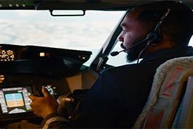
The light- and dark-blue cockpit trim is restful and, in a temperature of 23¡C, the APU air conditioning was very effective. To allow for full rearward travel of the control column, there is a deep slot in the Ipeco seat: the central safety-strap buckle is more convenient than a side buckle. It is easy to enter past the waisted rear-centre console, and two padded strips on each side of the overhead systems panel conceal a continuous hand-rail. Seat adjustment is smooth, but rudder-pedal adjustment requires the occupant to bend almost double.

The four-panel windscreen gives a fine view, and the lower left cockpit wall has a 240 x 160mm document hatch. The main circuit-breaker (CB) panel lies aft of the compact overhead panel. To save battery drain after a complete power failure, and to sustain 30min in instrument flight, then 30min in visual flight, more than two dozen CBs must be tripped. They are marked by white collars, and I suppose this saves on automatic off-load devices.

The Honeywell Primus 2000 integrated avionics system is standard, based on five 200 x 165mm screens: two primary flight displays (PFDs) ahead of the pilots; two multi-function displays (MFDs) inboard of each PFD; and a central engine-indication and crew-alerting system (EICAS). Apart from the PFDs, each has six soft keys on a horizontal bezel along its base.

Audible warnings vary with their severity: reds, displayed above the EICAS, merit a triple chime; ambers, shown on the top right of the EICAS, with blue status reminders, merit a single chime.

The required fuel load can be pre-selected, and is also displayed at the refuelling point under the right wing. The aircraft can be dispatched with a defective fuel-tank sensor, if a manual entry has been made. In flight, remaining fuel quantity is automatically computed from fuel flow. Refuelling takes less than 10min in a 20min turnaround.

A new flight-planning database was loaded in 20s from computer disc, into a unit in the right-hand avionics bay aft of the cockpit. Chief test pilot Meinhardt Feuersenger selected a test route in the flight management system (FMS) controller, ahead of the engine lever quadrant, and tracks appeared on the MFDs within 2s.

The top of the navigation display is a route-plan view, and the bottom a vertical profile (with up to five intermediate vertical constraints). The cleared altitude is shown as a dotted line across the profile.

There are two radio-management units (RMUs), each of which can be used to store 12 communications and 12 navigation frequencies, and display FMS auto-tuned frequencies.

Engine starting, via starter generators, is simple: switches on the overhead panel (which are left at "start" for rapid restarts in the air) are normally used to select power from one battery, but closing the DC main bus-tie enables both batteries to be used in cold conditions.

The high-pressure spool speed (Nh) grew so rapidly, to 10% ,that the condition levers were set to fuel-on at once; each starter cut out after 15s. They were then set to un-feather and the propellers quickly responded. Inter-stage turbine temperature (ITT) peaked at 640degreesC, well within its 850degree limit.

Engine primary parameters at idle were: 5% torque, 66% propeller speed (Np), 465degrees ITT and 75% Nh. Low-pressure spool rotation is indicated on the EICAS during start as a simple "NL"; its digital value appears on the engine systems page. Idle fuel flow was 120kg/h (265lb/h) each.

Ramp weight was 11,710kg with 2,040kg fuel and centre of gravity (CG) at 25.5%. The maximum ramp weight is 14,070kg; maximum fuel 3,310kg; and the full CG range is 22.5-40% of mean aerodynamic chord. Each torque-meter scale has a bug which displays calculated torque for all flight modes; for take-off this was set at 95.4% torque.

Take-off speeds on each PFD were selected through the soft keys on the EICAS bezel: when FMS memory and processing power is increased, this will be automatic. Decision speed (V1) was 112kt, rotation speed (Vr) 117kt and airborne safety speed (V2) 119kt (220km/h), for a 12degree flap take-off. V2 at maximum weight would be 133kt.

SMOOTH MOVER

The Dornier 328 started rolling as soon as the brakes were released. As we taxied, I tried out the brakes - gently at first, as the anti-skid system is not effective until 30kt is reached. If a brake temperature exceeds 135degrees, a "brake overheat" warning appears on the EICAS. A "high-taxi" position for the condition levers, forward of the idle detentes, is used in strong tail-winds, or, if backing at high weight on one engine, to avoid a restricted speed band, and propeller internal resonance.

In a 90degree turn, at full 60degrees nose-wheel angle (100degrees is usable for towing with the steering arm still connected), the "spade-handle" steering tiller had a light feel. It is an unusual tiller: the grip has to be pushed both forward and down to engage. High turn-rate caused the high wing to heel gently on the 4m undercarriage track. Wing-tip minimum turning radius is 15m, well ahead of the cockpit and more than 1m beyond the tail's path. Minimum paved width for a 180degree turn is 14.5m.

A flap on each power lever releases the flight-idle detent for the propeller blades to operate in the beta range (direct pitch-control by power lever) and reverse. Beta indication on the EICAS is shown by a very small boxed "B" by the Np gauge, but the braking feel is unmistakable. When I nudged back on the levers, to control speed without using the brake, the aircraft slowed smoothly.

To sample backing-up, I left my feet on the floor, and gave the propellers a burst of reverse, promptly released to avoid the aircraft racing backwards. Steering held steady during backing, as the nose-wheel does not trail. On Feuersenger's suggestion, I tried controlling speed and direction using engine power alone: the experience was like steering a flying boat at low water-speed.

The control checks were carried out using Dornier's neat display on one of the MFDs: on a skeleton view of the wing seen from the rear, of the fin and stabilise, the control surfaces appear as blue rectangles which grow to track deflection until they touch full deflection markers. If a surface is forced beyond its stop (or if a stop is ineffective) it shows as a yellow cross.

The main warning for an incorrect take-off configuration is a pulsing horn and a red light; incorrect parameters, which are spelled out on the EICAS, include unarmed auto-feathering or condition levers not set at maximum propeller speed. (This maximum is set at the last moment before take-off, since it disables the tiller steering, which can be disconcerting at first.)


DOWN THE RUNWAY

Peda- steering authority is +/- 10degrees. After slight initial weaving, I got the feel, and the rudder became effective well before 50kt. was reached. The maximum-weight take-off distance under standard conditions is 3,570ft (1,090m) - we covered about 870m.

Initially, the weight of the elevator forces the control column forward. As it starts flying, the pilot has to gently resist a backward movement of the column. On this occasion, the elevator trim was at exactly mid-range, giving an easy lift-off. As the airspeed increases, there is a significant pitch up, and I was soon using the dual-rocker trim switch on the control wheel to compensate.

This pitch-up momentarily balanced a slight sinking as the flaps were retracted at 140kt. At 400ft radio height, those alerts inhibited at take-off are re-armed and the green torque bugs drop back to their "climb" settings. Np was cut down from 1,300RPM to 1,100 RPM (84.6%): the reduction in noise, even in the cockpit, was marked.

The white bugs on the Np scale went blue when the synchronisation was armed, and turned green when both Nps entered the climb (or cruise) range. It is important to retrim the rudder with power changes; the electric trim is fiddly, using two co-axial knobs on the centre console.

Roll control had stiffened at the 200kt normal climb speed, but a 30degree bank could still be reversed in a rapid 4s. A limiter restricts maximum rudder deflection above 160kt, and firm foot pressure with hands off the control wheel, induces bank only slowly.

The stiff directional stability is due to the dorsal and ventral strakes. Dutch Roll (more roll than yaw) is not easy to induce, and is damped to half amplitude in under two cycles. At lower speed it is similar, but with more yawing.

As true airspeed increased in the climb, the low engine noise made cockpit airflow-noise more noticeable. The climb speed was Mach 0.40 above 15,000ft (performance climb is flown at 155kt and M0.38 above 25,000ft). Our climb continued to the 31,000ft ceiling. A trend bar on the altimeter scale, as on the airspeed scale, neatly shows how much height will be gained or lost in the following 6s. The climb rate decreased from 1,750ft/min (8m/s) at 15,000ft to 1,550ft/min at22,000ft, but was still over 1,000ft/min nearing 31,000ft - an average of 1,200ft/min over the 24min from take-off.

The torque bugs move to compensate for ambient conditions, air speed, ECS bleeds and condition-lever position: they had fallen to 66% Tq at 25,000ft, with a steady 96%Nh and 700degreeC ITT through the climb, while fuel flow fell from 380kg/h per engine at 12,500ft to 225kg/h at 30,000ft.

In the cruise, Np is set to 1,050RPM (80.7%): this may seem only a small reduction, but it further reduces noise in an already very quiet cabin. The noise attenuation devices are tuned both to the climb and cruise Np (see box).

The climb attitude, which had been 5-6¡ nose-up at 200kt and 7-8¡ in performance climb, dropped to a comfortable 2.5¡ in cruise at 190kt/Mach 0.53 - a true air speed of 307kt. Each engine was now burning 230kg/h in ISA conditions.

The mode-selector panel of the digital autopilot, flanked on the glare-shield by the two pilots' EFIS display controllers, has simple push-buttons rather than switch-lights. The phased-array radar allows each pilot to control the weather overlay on his MFD independently, between +/-15¡ tilt, and to show ground-mapping or weather. When sunlight strikes an EFIS screen, an automatic control is designed to adjust its brightness in 2s. To demonstrate his confidence that the APU can supply both air and electrics anywhere in the flight envelope, Feursenger switched off one generator. The APU generator took over its load and finally easily sustained all electrics. Then the air bleeds were switched off, leaving the APU "running the entire show"!

No warnings show up on the EICAS if a deliberate action is taken, and no supplies are interrupted. A status reminder of this extreme configuration might be justified.


CABIN COMFORTS

The maximum pressure differential of 0.465 bar (6.75lb/in2) maintains an 8,000ft cabin pressure at 31,000ft. There is little noise from the air-conditioning noise, and the rear cabin is naturally quiet - but the noise-attenuating devices achieve the unnatural for a propeller-driven aircraft!

In both climb and cruise (at the specified Np settings), the 30- to 33 -seat cabin is, in relative terms, "all-over quiet" at all airspeeds - with unexpectedly low noise levels when seated or standing in line with the propellers.

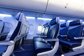
The baggage bins, along the right side only of the 1.89m-high two-plus-one cabin, take full-sized flight-bags. The bins have concertina-type doors to reduce the space intrusion of opened conventional doors or swing-bins. The window seats do not butt up against the wall trim, leaving plenty of room for passengers' feet, and the aisle - of 430mm minimum width - allows 460mm passage at body level.

The gear does not need to be extended for an emergency descent: the big propellers are speed-brakes enough at flight idle. To assess high speed in descent, the autopilot was disconnected (it biases the nose up at maximum operating Mach number of M0.59) and power was left on.

The rate-of-descent scale extends to 3,000ft/min; higher rates are shown only digitally. The airspeed-scale digits turned yellow as the 10s speed-trend vector reached Mmo, and a warning sounded as speed entered the red sector above: the controls were inevitably stiffer at M0.60, and a roll to 60¡ took 5s to complete.

Dornier promotes the 328's high speeds, including in descent, as making it compatible with jet airliners, and giving it some edge over its competitors, especially at high altitude. At 20,000ft, the cruise speed was 237kt IAS and M0.52; a TAS of 322kt was obtained at 85.5%Tq with a 320kg/h fuel-flow. A TAS of 335kt could be expected at 95% maximum take-off weight and typical CG in a production aircraft.

With the aircraft in a 45degree bank, at 20kt above stall-speed, the flight-director and the aircraft symbol on the PFD lacked the fidget that is sometimes seen, and steep turns were made accurately on this reference alone. Once there is more than 4degrees upwards aileron deflection, the appropriate roll spoiler discretely provides assistance. At bank angles over 65degrees, or with more than 30degree pitch-up or 20degree pitch-down, superfluous information is removed from the PFD screen.

The pilot must be ready for "ballooning" up as 12degree flap is deployed, to avoid gaining altitude. As it runs to 20¼, there is less trim change, but the nose drops by 3degrees. With 32degree flap, the nose lowers 3degrees more, with a slight rumble at the 160kt maximum speed for this much flap.

Selecting landing flap triggers no irritating "gear-up" warnings, which only come into play below 400ft radio height, but extending the nose-gear does increase cockpit noise noticeably.


STALLS

A red under-speed bar moves down the speed-scale with each flap extension. The autopilot supplies no low-speed protection except for disconnection as the stick-shaker comes in, when the airspeed-box digits turn red. Angle of attack, earlier displayed on the PFD, has proved not to be needed

The stick-shaker is unusual - both tactile and aural - it is a clapper in a housing and sounds like a bell. The action of the stick-pusher is not harsh: at a slightly forward CG, there was a tremor of natural buffet just on the push.

The ventral strakes then take effect, as the nose tips steeply down. We reached 20degrees nose-down with my hands merely resting on the control column: indeed it is better not to add to the push. (Dornier fitted a pusher only to facilitate flight testing and certification, and now says that it is not needed.)

The ensuing speed increase was rapid, and immediate recovery could be made without much risk of a secondary stall, typically within 500ft or so. Stall speeds at maximum weight range from 113kt clean down to 91kt with 32degrees flap; at our weight of 11,000kg they were 10kt less. An extra protection is an upward bias of 10kt on stall speeds when the elevator-horn electric heat is on. Thus, with icing risk identified, the angle-of-attack triggers for shaker and pusher are advanced.

The standby gear-lowering is armed by opening a cover at the rear of the centre pedestal to reveal a telescopic lever. I pulled the lever up, locked its knob forward, and moved it sideways; back pressure was felt immediately, after which just one movement left and right released the gear, to quickly lock after free-fall without any further effort..

We checked a slam acceleration from flight-idle to full power: it took 6s. If an electronic engine-control fails, a hydro-mechanical control to a pre-set fuel schedule takes over.

Then, with the aircraft configured for a simulated final approach, we tried an abused rotation into a go-around at 9degrees/s pitch-up rate, when a good feel in pitch was sustained. Operating throttle-mounted buttons moves the torque bugs to go-around power.

Next, we moved the right-hand engine to idle. With just 76% maximum torque available at 15,000ft on the left engine, a speed of 103kt was easily held with the wings level. This gave a feel for the Vmca of 105kt with a propeller feathered. Single-engined manoeuvring at 120kt was easy, without retrimming the rudder.

At 130kt IAS, 15degrees of sideslip could be held on a constant heading with the rudder nearly fully deflected: the wing wanted to roll level in very positive lateral stability. Two vortex generators, added close to the forward top of the fin, prevent elevator blanking at extreme angles.

The FMS permits the selection of a vertical "go-direct", and a new descent path back to Dornier's Oberpfaffenhofen airfield was quickly defined. Approach limits, on the barometric and radar-altimeter scales, were reset at the push of a knob to the commonly used figures of 1,500ft minimum altitude, or 200ft radio height, to be finally adjusted with less fiddling with the standby flight instruments.

In the navigation display "preview" mode, VOR or ILS course lines and glide-slope deviation can be displayed in blue or white on an MFD; this, with bearing pointers, shown "under" the magenta FMS display, is most useful in intercepting one mode from another.

We flew one approach with the EFIS and EICAS brightness turned to zero, to simulate a complete failure, and I had to adapt quickly to the standby flight instruments. The basic layout is effective, with standby attitude indicator and combined airspeed/altimeter one above the other, left of the EICAS. These line up with the left RMU below, which can present a very full-format navigation display, while the right RMU can show up the engine displays and up to seven EICAS-style amber alert captions, to cover major failures.

The 11,000kg approach reference speed Vref was 101kt. We made a Cat 1 ILS approach, with Feursenger calling the torque and localiser or glide-slope deviations. Approach torque is 20-25% (35-40% on one engine). We arrived "on the button" for a go-around from 200ft, without cheating on my part. It was hard work, but possible without any training.

For a steep approach Vref is 109kt for all landing weights. We used separate modified precision-approach path indicators, set at an angle of 6degrees. They show steady white or red for high or low, and flash at greater deviations. From a high start, on runway heading, the descent path was nearer 7-8degrees before we settled into the slot.


STANDBY SUCCESS

With a short intermediate flare, the Dornier 328 was rounded out "on to the numbers" and brought to a full stop. It would require a gross over-flare and heavy landing to invoke the attitude limit of 9degrees. The optional lift-dump (using inboard pairs of spoilers on each wing) reduces the landing distance by 150m. It is due to be certificated this month.

A final take-off was made with a simulated right engine failure at V1, with no unexpected reaction. Single engine climb speeds range from 122-137kt clean, according to weight.

After the final touchdown, with the nose-wheel on the ground, I selected reverse on the left engine only. The aircraft can be kept straight with rudder into the dead engine, but a lot of aileron is also needed, to stop the greater lift on the "dead" side from lifting the wing. Single-engined taxiing, and a tight turn into the live engine to the parking spot, presented no difficulty.

The Dornier 328 is extremely sophisticated for its size. Passengers will notice the cabin quietness; pilots will be impressed by its performance and by the Primus 2000. Many operators could find that it fits their books.


Dornier 328 development

The 328-110 has a maximum take-off weight increased by 350kg, and an optional ceiling of 31,000ft. Detail changes have reduced drag; take-off and landing distances are reduced by about 75m and 150m; and climb performance is improved. Range has been increased by between 300 and 500km.

The -120 will appear next November with PW 119Cs, whose 5% increase in thermodynamic power will boost hot-and-high performance, and increase single-engined ceiling by 1,000ft.

The -200 will have a "smart" rudder, giving a progressive reduction of authority with airspeed, but full rudder availability on engine failure; ground spoilers will be standard and a further 20¡ take-off flap setting certificated.


Avionics

The Honeywell Primus 2000 avionics system is based on two integrated avionics computers (IAC). IAC 1 includes the flight-management system and flight-guidance computer as two cards, each with dual microprocessors. Each IAC has a symbol generator, and either can service all five screens.

The system includes dual micro air-data computers and fibre-optic-gyro attitude and heading reference systems (AHRS); a Laseref III inertial system is an option. Equipment includes a dual radio-altimeter and X-band Primus 650 (or 870) weather radar and optional TCAS.


Cutting interior noise

Passenger cabin-noise attenuation is based on engine mounts, mass-dampers (on fuselage frames near the propeller plane) and bonded patches of multi-ply metal/composite on each rectangular area of skin between frames and stringers.

The engine mounts counter vibration at source, the mass weights primarily reduce low-frequency propeller noise, and the patches reduce high-frequency airflow noise. Bagged insulation material is spread between cabin trim and fuselage walls over the full cabin length, and the air-conditioning ducting has been "tuned".

Source: Flight International