Boeing and Lockheed Martin are proving they can build the JSF more cheaply than any previous fighter

Paul Lewis/FORT WORTH Guy Norris/SEATTLE Graham Warwick/WASHINGTON DC

Much of the manufacturing technology that the Joint Strike Fighter (JSF) requires to meet its aggressive affordability goals is being piloted on current production programmes. Early experience is essential if the competing teams are to provide the data needed to support the cost proposals they will submit later this year.

Fabrication and assembly technologies not yet ready to pilot on production programmes are being matured in the concept demonstration phase, at the end of which both teams will have built most of the major parts of their preferred weapon system concepts (PWSCs) - the JSF designs they will propose for engineering and manufacturing development (EMD).

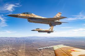
For Lockheed Martin Aeronautics, the F-16 fighter programme has proved fertile ground in its drive towards lean manufacturing. The need to cut unit costs while simultaneously reducing production from its peak of 16 a month to between two and four means the F-16 programme is acting as a lean learning model for JSF, says Larry Pike, director lean deployment and process improvement. Overall savings from lean implementation on the F-16 programme promise to be substantial. "We think an easy 50% in terms of space and a 60-80% reduction in terms of span time," says Pike.

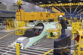
Redesign of the Fort Worth factory along lean lines has reduced production span time for the fighter from 36 months. "An F-16 takes 22 months to produce now," says Pike. "I can see 12 months in my headlights, no problems." Lean processes have been deployed on the fin, inlet and forward fuselage. Lockheed Martin plans to finish implementing lean forward-fuselage final assembly by the year-end, "then move out to the flight line, which is a pretty small segment" . The critical path for aircraft production will then have been converted to lean. "At that point, we are going to come back in and do the centre and aft section," says Pike.

Just in time

Lean methods take many forms, from putting tools and parts within easy reach of workers, to redesigning assembly procedures to "reduce variability, congestion and confusion". Tools and parts for a task are pre-kitted and delivered to the point of use "just in time". Hand-held radio-frequency barcode readers record the arrival of kits on the loading dock and their departure for the assembly line, and alert suppliers to build up and ship the next kits. "We have a week's worth of inventory at any one time," says Pike.

A contract to produce F-16 wing pylons housing towed decoy dispensers has been used to pilot lean production. The planning process included bringing an Indy race car into the factory to demonstrate the team approach to pit stops. The first pylons took 126h to assemble. Over 200 units later, "we're at 31h", says Pike. "At the same time, we're driving the cost out and the quality up." Originally, the contract was for 350 pylons, but is now for close to 1,000, with orders for another 1,000 in the pipeline - "all as the result of unit savings", he adds.

Such savings, if they can be carried over to a complete aircraft, will be essential if the JSF's unit cost goals are to be achieved. Pilot programmes like the F-16 pylon provide valuable data to validate the cost estimates that the Boeing and Lockheed Martin-led teams will use in their EMD proposals. But they are not enough. Both teams are relying on technology that is not yet mature enough to insert into production programmes like the F-16. As a result, they have had to conduct large-scale demonstrations to substantiate the cost savings.

Boeing believes savings demonstrated by manufacturing advances developed for the concept demonstrator aircraft (CDAs) are as important to the JSF competition as the design itself. Each team has built two CDAs. The hallmark of Boeing's X-32 programme has been its use of CATIA three-dimensional (3-D) solid modelling techniques. "We went to the next step with 3-D solid modelling and broke away from the traditional way of doing things," says director of JSF affordability Dave Brower.

Digital definition

"The various parts of the aircraft - the forebody made in St Louis and the mid-fuselage, wing, aft fuselage and tails made in Seattle - were all designed and made off the same database. In the past, we'd pass it off to manufacturing to write a numerical code [NC] to run four or five machines, then run a piece of wood or aluminium to check everything was OK. But this time, we took the digital definition of the part and ran it through an automatic NC generator. So, in effect, we did a simulation of a simulation. The result was the first pass was good, and we saved lots of time. Past programmes took five weeks from release of the part design to cutting of the actual part - but on this one it took five days."

The new process embeds volumetric removal instructions in the component-design database. The information is downloaded to a numerical control code generator, which creates a machining tape. After a few simulated runs, the first part made with the NC program is the first production part for the actual aircraft. The automatic NC generator is a blend of CATIA and Unigraphics - the heritage computer-aided design system used by McDonnell Douglas - and eliminates the potential for human error in writing code.

High-speed machining is a key manufacturing technology for JSF. As well as producing lighter, larger parts that simplify assembly, high-speed machining is an enabling technology for achieving commonality between the three variants - conventional take-off and landing (CTOL), carrier capable (CV) and short take-off/vertical landing (STOVL). Commonality is the raison d'être of the JSF programme and the foundation of its affordability.

"The hardest part of JSF is the J," says Martin McLaughlin, Northrop Grumman airframe and manufacturing integrated product team lead for the Lockheed Martin JSF. "We know we have to come up with a family of aircraft and the airframe, in particular, is not going to be one size fits all. If you take cost versus commonality, there is a bucket in the curve. There are big benefits at first, then [cost] goes through the roof. The secret is to find the middle ground. We think the middle ground is removing any need to hand finish [a part]."

Achieving this goal relies on high-speed machining. "We're getting two-thirds saving compared to conventional NC machining, "says McLaughlin. "About half that saving is due to more efficient metal removal rate - taking material out more quickly. The other half is due to the quality of the finish - there is no longer any need to hand finish."

The low reaction forces generated at spindle speeds of 30,000rpm or more mean that parts do not need to be supported by dedicated mill fixtures while being machined. All they need are lugs to hold the billet down, which are later machined off. "If we were doing it the old way, we would have to have CV, CTOL and STOVL mill fixtures," says McLaughlin. "In fact, we would need three each for the first, second and final machining stages."

Batches not needed

To cover the time it took to retrieve each mill fixture from storage and the cost of setting up, parts had to be machined in batches in order to be efficient. The parts, in turn, then had to be stored. "Now you've got just plates of aluminum or titanium and when the time comes, the customer can say: 'I want two CTOLs, then a STOVL and then a CV and then back to three CTOL aircraft'. You just make the next component that is needed," says McLaughlin. "You don't have to make batches of them to recover mill fixture retrieval and set-up cost."

Eliminating mill fixtures is a "big deal", says McLaughlin, because it allows different parts to be milled out of the same plate. "You just go to a computer file and retrieve the correct NC program on the same milling machine and same bill of materials," he says. This reduces costs and increases commonality, allowing the production of "cousin" parts such as fuselage bulkheads - basically the same in all three variants but machined to a thinner gauge in the weight-critical STOVL than in the carrier-landing CV.

"Some structures are going to be different, but you want to keep that structure in the same location of the aircraft," says McLaughlin. "A lighter bulkhead for the CTOL/STOVL version for much slower, 10ft/s [3m/s] sink rates. In the CV, that's 27ft/s. It will need a much heavier bulkhead, but it's on the same fuselage station, locates in the fixture in the same fashion and in the same sequence." The secret to the J in JSF from an airframe standpoint is a common assembly sequence, says McLaughlin. "If you do that, you get economy of scale very similar to if they were common."

Electronic assembly

As with its 777, Boeing assembled its X-32 electronically before it began to put the aircraft together for real. "There were no physical mock-ups built," says Brower. "All pipes were pre-bent to fit, for example." Boeing even took advantage of the time difference with its partners to do work around the clock. "Fokker-Elmo, in the Netherlands, handled the wiring and, when issues cropped up, we were able to send a redesign digitally," he says. "Within 24 hours, they were shipping bundles of wiring out. It was so successful that the forebody was stuffed and completed with no trailing, out-of-sequence assembly work."

When parts began coming together at Palmdale, California, Boeing's chosen site for CDA final assembly, the fixed jigs traditionally associated with aircraft production lines were absent. Instead, major parts were placed on universal support posts and located in space using four Zeiss laser trackers. These are fixed to the floor in precisely known spots, which enables the trackers to act like interferometers, measuring the location and angle of each part in X, Y and Z co-ordinates. The system calculates where the part is relative to where the 3-D database says it should be. A video terminal on the assembly floor shows workers where the parts are, where they should be, and the deviation from each co-ordinate.

Clamps were installed once the parts were positioned properly. "The parts were so well defined, and fitted together so well, that we decided to go one step further and we started drilling fastener pilot holes while the parts were still being fabricated," says Brower. This worked so well that Boeing is using the technique in St Louis on the X-45 unmanned combat air vehicle programme, adding full-size holes during parts fabrication. "It looks like we'll be able to go to that in [JSF] EMD," he adds.

As X-32 assembly progressed, workers took to wearing a mini-computer hooked onto their belt. "Using a monocular eyepiece, mechanics were able to project the assembly sequence right over the part as they were putting it together and see what it should look like," says Brower. "It migrated from St Louis to Palmdale and then on to the maintenance people. It's turned out to be a very successful idea."

Major time savings resulted from the new assembly techniques. "We thought we could cut in half the time it took for alignment between the forebody and mid-body compared to the YF-22," says Brower. "In actuality, the forebody came in at one-third the time. We did the forebody of the X-32B in a third less time again than that of the X-32A. On the mid- and aft fuselage for the -32A [all titanium], we estimated the work package at half the cost of the YF-22. It actually came in at a third."

Boeing is already planning improvements to the assembly process for the production JSF, drawing on lessons from other programmes. "We want to produce three different versions on a linear line, but we don't want to move anything by crane." says Brower. "Well, it turned out that the [AH-64] Apache line transitioned in 1998 to a linear pulsed line. By doing this, they had reduced it from 19 line positions to 10 and cycle time from 81 days to 44 days." As a result of the line change and other lean initiatives, flow time on the AH-64 line is running at about 35 days per aircraft. Final assembly cycle time has been reduced by 60%.

Using the same concept, Brower believes Boeing can meet the JSF production demand with a seven station line. This could build up to 17.5 aircraft a month, with an on-time residence at each station of 1.5 days. Aircraft would move down the line in mobile docks or tools (not jigs) for the first four station positions. From station five onwards, the JSFs would move down the line on their own wheels, while the mobile docks would cycle back to the start of the line to receive the next aircraft.

Airframe affordability

Lockheed Martin placed less emphasis on proving manufacturing technology with its X-35 concept demonstrator aircraft, and more on conducting unique airframe affordability demonstrations. This approach allowed the team to freeze the design of its CDA, then continue to evolve the configuration and conduct airframe manufacturing demonstrations that were more representative of the PWSC that will be proposed for EMD.

"We exercised the entire industrial base at Fort Worth, Palmdale, El Segundo [Northrop Grumman] and Samlesbury [BAE Systems] and also demonstrated industrial manufacturing techniques with some depth," says McLaughlin. "We produced seven large sub-assemblies and collected them at Fort Worth. If you count a little bit of left-to-right symmetry [only half a wing and half an inlet were built], and forward and aft similarity, we covered 80% of the PWSC."

One of the more important demonstrations was the assembly of a wing carry-through structure representative of all three variants, with the CTOL/STOVL structural arrangement on the top and the CV on the bottom. "We did this to show we would have an economy of scale between the two, even though they were tailored quite a bit different for navy arrested landing and STOVL integration," says McLaughlin. "We think you need a bigger wing for the CV to have the carrier handling properties, but we want to keep commonality."

The team also built a section of forward fuselage to demonstrate quick mating between the wing and centre section. "We build the aft fuselage in Samlesbury and we also mated it to the CV wing and centre that were previously joined," says McLaughlin. "We also did the inlet, a wing box for ballistic vulnerability testing, and a more composite forward fuselage including the first use of major assembly bonding." Most sections were built for further testing, not just show. The forward section has been pressure-tested to ultimate load and will be available in EMD for ballistic testing, already completed on the wing box.

Lockheed Martin has used the airframe affordability demonstrations to validate the structural concept for its JSF PWSC. This centres around combining metallic substructures with composite skins. "We thought long and hard about composite substructures," says McLaughlin. "What we did was minimise the amount of substructure by going to more load on the skin."

Composite panels

By using integrally stiffened composite panels, designers have been able to increase frame spacing from 125mm (0.49in) in the F-16 to 510mm in the JSF. This takes at least half the frames and bulkheads out. "This is all because of composites," he says. "If this was sheet metal, there is no way we would be there.

"It's also much cheaper to build skin than machine substructure parts, but the main benefit of wider frame spacing is it gives us better access for original system installation and particularly maintenance. A higher percentage of the load can be carried by the skin and less by the substructure because we know how to cost-effectively stiffen those skins."

The composite skins are integrally stiffened by syntactic film - epoxy resin filled with 20Ám-diameter microspheres and extruded as a film 2.5mm thick. During layup, composite plies and syntactic film is positioned using an overhead laser projector which reads CATIA data and picks up targets on tools to outline where each layer should go. "We use that to locate all the plies, but it's particularly useful for sheets of syntactic film," he says.

Use of composite skins carrying higher loads has meant developing cost-effective inspection methods. Water-coupled ultrasonic inspection of composites has always been expensive, says McLaughlin, because the system has to keep two water columns either side of the part concentric. "With laser ultrasonic inspection, the incoming and outcoming beams are on the same side, so you don't have to match up with the other side and you can be off axis by up to 35í."

Other manufacturing technologies that Lockheed Martin has demonstrated include superplastic forming and diffusion bonding, a niche process for nozzle bay doors and speedbrakes where there is a high thermo-acoustic environment. Fibre placement allowed the team to produce one-piece inlet ducts and large unitised composite skins.

Outer limits

An important aspect of JSF assembly will be to maintain a precise outer mould line to meet low-observability (LO) requirements. "All aircraft until now have had the substructure built up and skins slapped on, showing the variation on the outside," says McLaughlin. "In the case of the B-2, that can be 60 thousands of an inch. Where two panels mate together, you get a step and have to hand-finish it. We have demonstrated a method of manufacture where we can get the skins to a theoretical outer mould line."

Access panels will be nested in one matched moulding process. "To meet LO requirements, they will be made to a very precise thickness to marry up with no protrusions," says McLaughlin. There will be no need to form or place a seal around a panel to maintain LO. "Every time a panel is accessed, the maintainer does not have to use any fill or fair or taping as on the B-2. This is what is going to make maintenance man-hours per flight hour for LO a fraction of what we've had before."

There will be a common, modular assembly sequence for all three Lockheed Martin JSF variants. "This is the secret to the J in JSF," says McLaughlin. "What we wanted to do is build the aircraft in parallel and have them come together quickly, rather than a long serial operation. You can only do this when you get to configure the aircraft like that in advanced design, so most of the work we've done in airframe and manufacturing over the past three years has been in deciding where the major module breaks are in this aircraft so that it is balanced and comes together quickly.

"We want to be able to build these modules and stuff them full of systems and then bring them together and mate them and not disturb those systems. The real secret was how to get these things to mate quickly without drilling in assembly."

There are four major modules: forward, centre, aft and wing. The wing upper skin is attached with 3,200 fasteners. "There would have been 9,000 if we had used traditional wing substructure spacing and broken the skin up into sections," says McLaughlin. "We get up to 1,500 holes on a single drill bit. That blew our mind - when you drill by hand you get 20, maybe 50. This is good evidence for digital control - no wobble."

The one-piece wing, with all equipment installed and the fuel system checked, will be mated to the centre fuselage without drilling on the assembly line. "The upper load path is continuous," says McLaughlin. "All aircraft since the early 70s have had a sidebody attach. That takes up a lot of volume, which we need for a weapons bay." For the X-35s, attachment holes were pre-drilled in the wing and centre fuselage independently, using digital data. "First time, we bought the wing in on an air bearing, spent 20min fiddling around and then all the pins dropped in," he says - all the result of 3-D solid modelling and NC control in fabrication and tooling.

Continuous section

The centre section is continuous to the weapons bay "because we don't want a break in the inlet", says McLaughlin. The only aircraft that have not broken the inlet into four or five pieces are the X-32 and X-35 CDAs, he says. "The secret is not just making a one-piece inlet, but integrating it with the aircraft without drilling it full of holes. If we had built this duct in the same fashion as the F/A-18E/F or F-22 duct, we would have 9,000 more through-the-duct fasteners than we have." The forward fuselage uses the same unitised structure as the inlet, with composite skins and space frames, but many more are co-bonded and only fastened where there are heavy landing gear loads.

The JSF assembly line will be built on a modular floor, a concept pioneered by BAE on the Eurofighter. The floor is raised on pedestals set in a 1m-square grid. "This was first tried at Samlesbury, with 11,000 pedestals," says McLaughlin.

Work stands, fixtures and cubicles have feet matching the grid, and can be picked up and redistributed around the floor. All utilities are under the floor. This results in a large open floor with no obstructions to moving vehicles around on air bearings, adds McLaughlin. "The assembly line can be re-balanced as we learn and production rates change."

Source: Flight International