Airbus is building on the systems approach it is taking with the A380 for the A400M - and the two aircraft have a lot in common
On close inspection it would not take the average aerospace engineer long to see the direct lineage between many of the major systems on the A400M and the A380 airliner now in final development just across the airfield at Toulouse.
Although a large proportion of the 80 significant systems on the A400M share design heritage and, in some cases commonality, with the A380, this does not automatically mean common suppliers. As part of its commercial approach, AMC is conducting a rigorous competitive evaluation and is on track to complete its selections by March 2005. "The programme is going according to plan, and so far we have about 50% selected," says systems aircraft component management team (ACMT) head Jean Michel Billig.
"The A400M is clearly an Airbus programme, so we're taking advantage of the family concept wherever we can. We don't want to reinvent the wheel so, for example, we have the systems architecture based on the A380, and half the spoilers are from the A340," he says.
However, Billig says the military role of the A400M means "clearly it makes sense to adapt where we can, but in certain cases because of the demanding EMI [electro-magnetic interference] and vibration environments we have to revalidate the concept. We have been running tests of the A380 IMA [integrated modular avionics] with Thales to validate it, and see it copes with the tough operating conditions. The results were positive, but in some areas it has not been possible, so we have had to run a development programme for additional military features such as the radar, surveillance and navigation."
A400M central programme office engineering systems director Sergio Llamazares adds: "We're also trying to use the A380 example as much as possible to keep development time down." A prime example of this is the automatic flight system (AFS), which builds heavily on the A380 flight- control system to provide flight guidance, envelope protection and flight management functionality. "It's almost exactly the same technology, apart from some changes tailored specifically for the A400M's particular military needs," he says.
Flight management
One of these changes is the unusual use of the flight-management system (FMS), and the specially developed military mission management system (M-MMS), to provide low-level flight guidance to the AFS. "Low-level flight will be implemented in the FMS, in conjunction with the M-MMS, that's a novelty for this particular aircraft," says Llamazares, who adds that the same systems will also work together to provide guidance for air refuelling. For low-level flight, the system is designed to allow safe flight at 500ft (150m) above ground, in instrument meteorological conditions on a pre-defined route and altitude.
Developed by EADS Defence Electronics in Ulm, Germany the M-MMS feeds the AFS and Thales-developed FMS with digital terrain elevation information for the low-level flight mode, as well as providing the optimum release point for air drops. The M-MMS is a key part of the aerial delivery system as it computes the drop point from the cargo loads and cargo loading/unloading databases, as well as providing the best cargo loading and unloading arrangements for both tactical and strategic missions.
The flight-envelope protection feature, which allows the crew to get the maximum performance from the aircraft without over-controlling or over-stressing the aircraft, is also a key feature - particularly in an aircraft tasked with so many potentially unusual manoeuvres such as the A400M. "We are still discussing this with the customers," says Llamazares. "Obviously we will be allowing it to go further [than the A380], but it still has to offer protection and we are still defining exactly what this will be - both in automatic and back-up modes."
The final limits are due to be defined at the turn of the year before the end of the aircraft definition phase in the first quarter of 2005, but they are expected to allow bank angles up to 120°, or double that of the commercial aircraft.
The M-MMS also hosts several other functions, including the mission planning and data retrieval system, the tactical ground collision avoidance system (T-GCAS) and the tactical threat database. This latter function is a database that provides all known threats to the crew via the navigation, tactical and multipurpose display and control display units.
Communications data such as frequency tables, auto-tuning and EMCON (emission control) are also housed in the memory of the M-MMS, which additionally acts as an interface between the cockpit display and the communications system, allowing the crew to control the appropriate transceivers.
The communications system is a sophisticated union of commercial and military radio suites. Linking the two is the military mission management computer (M-MMC) which "is a kind of bridge between the 1553B databus and the AFDX of the A380", says Llamazares. The 1553B databus provides the standard military connection to systems such as the MIDS secure tactical datalink and IFF (identification friend or foe) transponder, while the Ethernet-based AFDX backbone links the bulk of the communications systems.
"It's a new concept, but we decided to do this because we wanted to keep the risk as low as possible. We had already started the A380 development, so for the civil part of the A400M we're trying to use as much of that as we can. However, at the same time, we also needed to implement the military business, so we decided this was the best way to go," Llamazares says. The M-MMC therefore provides a bi-directional gateway between the military and civilian data highways and allows the crew to manage the 1553B remote terminals as well as civil and military radios from the cockpit through a single centralised communications management system (CMS). The core software of this runs in the M-MMC.
As well as MIDS, IFF and the usual HF/VHF/UHF radios, the CMS is also designed to manage Selca (selective calling), Inmarsat satcom (available as an option), the various audio systems (including a wireless intercom, cockpit voice recorder and passenger address), emergency locator system and Comsec radio encryption/decryption system. Suppliers for the bulk of the system will be downselected in November, says Llamazares.
Flight control
As an outgrowth of its A380 FCS foundations, AMC is developing its own flight control computers (FCC). Four of these units will provide the heart and mind of the A400M fly-by-wire flight control system, which continues the long-established heritage of the Airbus commercial line. "We're doing this ourselves because of the very specific requirements of the aircraft. Although it will essentially be the same hardware as the A380, we will have to qualify them as new computers because this aircraft is powered by four turboprops instead of turbofans," he adds.
As with the civil Airbus family, the A400M flightdeck will be equipped with sidestick pilot controls. Through the FCCs, these command a piloting objective and not simply a control surface deflection. The commands also include load factor in pitch and roll rate in roll, which in certain conditions will be selectable under a "select and release" technique to reduce workload.
The FCC commands are processed through two channels, one of which controls and the other monitors. If the system detects a disagreement between the two, the problem computer is automatically disengaged. If all four FCCs fail, an independent electrical control system takes over to control the aircraft in roll, pitch and yaw.
Flight-control signals are transformed into movement by a redundant set of 20 servo-controls and actuators, seven on each wing and six in the tail. To ensurea higher level of tolerance to battle damage, and to build in the same levels of system robustness established for civil certification, the FCS has dissimilar flightcontrol power sources for the rudder, ailerons and elevators.
The rudder is actuated by two electrical back-up hydraulic actuators (EBHA), each powered by one hydraulic and one electrical system. The actuation of the ailerons and elevators, in contrast, is provided by an electrically powered electro-hydrostatic actuator and a conventional hydraulically powered actuator.
The spoilers, five of which are mounted per wing, are powered by one hydraulic system that is arranged so that it provides symmetrical spoiler actuation on each wing. Flaps and tailplane trim are powered by two hydraulic circuits. "Once again we have adopted the A380 architecture and even the same actuators to reduce risk," says Llamazares, who adds that system suppliers include Moog and Liebherr.
Electrical power
Electrical power generation, important to all fly-by-wire aircraft, receives particular attention on the A400M with its widely differing civil and military systems. The broad power frequency needs in the 300-400Hz-plus range drove AMC to the use of variable-frequency generators (VFG) as the system of choice for AC power. One VFG will be attached to each engine, providing four separate sources of a nominal 75kVA. Additional AC power will come from a three-phase 90kWA generator on the auxiliary power unit (APU), a similar generator on the ram air turbine (RAT), and an emergency battery that feeds a static inverter.
Llamazares also describes the choice of the VFG as a "novel" successor to the similarly configured A380, which "broke the existing monopoly" by being configured with the VFG architecture. "The A400M is a kind of follow-on to that decision, but the main influence was the fact we would have to qualify a wide range of power demands."
DC power is provided by three 300A battery charger rectifier units (BCRU) and a single transformer rectifier unit (TRU). Two of the BCRUs feed the DC main bus bars and the third supplies the flight essential bus bar. The TRU provides power to the APU starting system.
The relatively large wing of the A400M provides ample room for a fuel system comprising three tanks per wing and a large centre wing-box tank. Overall capacity, not including the production-line provisioned 3,000 litre (790USgal) cargo hold tank, is 60,000 litres.
"This was based on the operational needs of several of the customers," says Llamazares, who adds that the final layout of parts of the pipe routing for the system is "still being refined".
AMC has opted for simplicity where possible, and the fuel system is a classic example of this, having basic management procedures and two fuel burn sequences for logistic and tactical missions. The system is also adaptable to the aircraft's expected role both as a receiver and in-flight tanker. As a receiver, the aircraft is provisioned with a removable in-flight refuelling probe mounted in the crown above the flightdeck. As a tanker, the fuel system is provisioned for wing-mounted refuelling pods as well as an optional centreline hose drum unit (HDU) in the rear fuselage on the main cargo deck.
Refuelling fuel is routed from the cargo tanks and larger wing and fuselage storage tanks to the HDU and pod dispensers through a separate system from the engine fuel feed. This latter takes its immediate supply from the two outermost of the three wing tanks. Inner engine feed fuel comes from the centre of the three wing tanks located midspan between ribs 12 and 17, while fuel for the outer engine comes from the outboard feed tank running out from ribs 17 to 22.
Outboard even further is a surge tank running from ribs 23 to 25 containing the pump and non-return valves of the scavenge system. The overall capacity has been boosted by the recent decision to droop the wings by a further 2° by increasing anhedral to 4°.
Fuel and hydraulics
A series of optically based sensor probes are planned for each tank cell to provide accurate data on contents regardless of inter-tank valve operation, all of which will be digitally displayed on the flightdeck. The aircraft will also be provisioned for an optional OBIGGS (onboard inert gas generator) fuel-tank inerting system that will use bleed air direct from the engine rather than have the additional weight and complexity of a dedicated compressor. The air will be forced through separation modules to release nitrogen, which will then be pumped into the fuel tanks as they empty.
High-pressure engine-driven air is also the main source for the pneumatic system that provides air conditioning, ice protection for the engine intakes and wing, and pressurisation of the cabin and several on-board systems. Two computers will control the system, each having duplicated circuitry to control the four engine bleed systems. The two computers are also cross-linked to transfer and monitor functions in the case of a failure. Pressure relief devices are plumbed into the ducting of the system in areas where ruptures could be dangerous, and a leak protection system provides warning of any ambient overheating.
One area where the example of the A380 is not followed quite so closely is the hydraulic system that operates at a maximum pressure of 207bar (3,000lb/in2) compared with the 345bar of its bigger civil sibling. "There was a thought at the beginning to follow the A380 to save weight, but the justification was not really there because of the smaller overall size of the A400M," says Llamazares, who adds: "We are about to select the hydraulic system pump supplier."
'Iron bird' tests
The system itself is divided into blue and yellow circuits, with power provided by four engine-driven pumps - two for blue and two for yellow. Electrical pumps and accumulators can also provide back-up hydraulic power, while a hand pump can be used to power the cargo door and rear cargo ramp. The hydraulic system is due to be installed in an "iron bird" test rig in the first quarter of 2006.
The landing gear is powered by the yellow system, as is the nose gear steering. The undercarriage is modelled on the Transall C160 and forms one of the most critical aspects of the A400M design. Built for rugged performance, short-field take-offs and landings and soft field capability, the 14-wheel undercarriage consists of a two-wheel nose gear and a pair of tandem multi-wheel main landing gears housed in large sponsons. Each main gear is made up of three independent lever-type struts with twin wheel, brake and tyre assemblies. Messier-Dowty and Messier-Bugatti are developing the main gear units, with the brake and wheel supplier still to be decided.
"We have specific requirements for landing in soft ground at tactical weight, which this is designed to meet," says Llamazares, who adds: "We also have to fulfil the requirements for operating from uneven surfaces, which is really tough. The design is therefore baselined on the C160, though with much more weight capability." The gear units retract aft into the sponsons and are electronically controlled and hydraulically powered.
As the main gear is made up of three sets of independent single-stage shock absorbers per side, loads are efficiently transferred into the fuselage structure while at the same time allowing for a relatively low-profile sponson shape. The concept also lends itself to better performance on semi-prepared strips, and supporting a low cargo floor. Tight turning capability is also enhanced by a selector valve that allows the front leg to be raised away from the ground.
This changes the load distribution of the forward main gear and, together with selective actuation of the multi-disc carbon brakes, gives the aircraft an undercarriage turn radius of 15m and an overall turn radius of 28.6m. The A400M will also be able to reverse up a 2% slope on hard ground using its own power, or up a 1% slope in soft ground at its tactical maximum take-off weight in hot and high conditions.
Kneeling feature
Another feature of the main gear is a set of hydraulic chambers that can be filled to raise and lower the rear fuselage by around 2°. The main gear, together with its unusual "kneeling" ability, will be tested in a separate rig to be created by Messier-Dowty, says Llamazares. The nose gear is relatively conventional, but does have an unusually large 600mm (23.6in) stroke.
The gear is designed to provide sufficient flotation to carry useful loads on 925km (500nm) tactical missions into unpaved forward airstrips with load-bearing ratings ranging from four (usually turf surfaces) and six to eight (moist sand) all the way up to crushed rock/concrete surfaces with ratios of 80-100.
The tactical utility of the A400M is also reflected in the sophisticated lighting array carried by the airlifter. In addition to the standard civil European JAR 25 compliant navigation, anti-collision, wing and engine inspection lights and landing lights, the aircraft is fitted with a suite of military-unique illuminations. These range from fuselage, wing- and tail-mounted formation flying lights to external and internal cockpit lighting and is compliant with night-vision-goggle (NVG) operations. Lighting is the overall responsibility of TAI of Turkey.
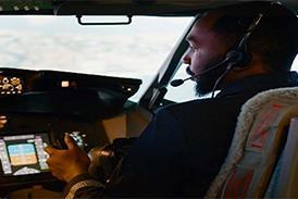
Based largely on the Airbus cockpit philosophy, the A400M flightdeck is designed for two-crew operation and features sidestick controllers, and up to nine full-colour, large-screen interchangeable displays.
The design incorporates an optional position for a third flightdeck crew station immediately aft of the centre pedestal. The position is provided for complex tactical missions, and is augmented by space for a fourth crew position in a folding seat by the side of the flightdeck, adjacent to a crew rest area with two bunks. Aft of the bunks and an avionics rack is a galley area.
Thales and its German subsidiary Diehl Avionik Systeme are supplying the control and display system (CDS), which is derived directly from the A380 flightdeck.
Comprising eight 150 x 200mm multifunction liquid-crystal displays (nine if the optional third crew station is installed), the system provides the primary flight display, navigation and flight management display, communication and surveillance management, engine and warning display, systems and tactical display, tactical situation management, digital map, video, an air-to-air refuelling display dubbed "give and take" and a formation-keeping system display.
Thales, which is developing the CDS at its Bordeaux site, is also providing the cockpit's two foldable head-up-displays (HUD). The units, which are being developed in France and the UK, use active-matrix LCD technology and provide guidance for parachute dropping, in-flight refuelling and threat warning in addition to the standard flight guidance and landing information.
The flightdeck design is close to being frozen, and a "Class 2" mock-up willbe complete in October 2005 to aid development of the NVG-compatible lighting and other systems. The developmentsimulator, which will help in the development of flight-control laws and crew workload evaluation, enters service at the end of this November.
Although modelled on the Airbus flightdeck, there are several detailed differences as a result of input from the national customer group and the extra military system features. For the first time on any Airbus flightdeck, for example, the airbrake control is mounted on the throttles "because there is just not enough room on the pedestal", says mock-ups and simulator concepts manager Bruno Taffett.
Evaluations of the flightdeck ergonomics have taken place with customer test pilot group, with pilots dressed for the "worst case scenario in oxygen mask, and wearing NVGs", says Taffett. "They wanted a few changes, and all of them wanted to move the emergency fire extinguisher control panel further forward." Other details such as the cursor control device (a joystick with a lever) and the modified nose gear steering handle have yet to be installed on the simulator.
GUY NORRIS / TOULOUSE
Source: Flight International