Bombardier's new Learjet 45 business jet proves pleasant and easy to fly

Peter Henley/Wichita

In the late 1950s, William Lear designed a small twinjet aircraft for business use with performance comparable to that of the jet-powered airliners of the day. Lear established a modest production plant at Wichita, a Kansas town already steeped in aviation, being home to Beech and Cessna. The Learjet prototype had its maiden flight in October 1963 and was immediately successful.

Learjet was acquired by Bombardier in 1989, bringing about the combination of Learjet's range of business jets with Bombardier's larger Canadair Challenger and, latterly, Global Express. The latest addition to this family is the Learjet 45 light business jet, an eight-seater with a nominal 3,700km (2,000nm) range.

Although it has a strong family resemblance to its brethren - sharing the T-tail, winglets, "delta fins" and trademark Learjet windscreens of the Models 31A and 60 - the Learjet 45 is a totally new aeroplane. The goal was to design an aircraft which combined good low-speed handling and high-speed performance, and which could be produced at a cost which would allow it to be sold at an attractive price in a competitive market. Bombardier is offering the Learjet 45 at a basic price of $7.9 million.

Despite all the careful thought and considerable investment, the Learjet 45's birth has not been entirely painless. The original goal of certification in December 1996 was not achieved. Provisional US Federal Aviation Administration certification was granted in late August and full approval is hoped for by October, followed in November by European Joint Aviation Authorities certification.

Production of the Learjet 45 has gone ahead, meanwhile, with more than 20 aircraft having been completed, enabling deliveries to start as soon as possible after certification is granted. So far, Bombardier has orders for 135 Learjet 45s.


Certification drive

Although the Learjet 45 team was busy with its drive for certification, Flight International was invited to fly the aircraft in early September. The third prototype was plucked from its daily chores in the avionics development programme, unpainted, untrimmed and fairly crammed with test paraphernalia. Despite being untypical of the production aircraft in several instances, this did not limit an assessment of its handling characteristics.

A walk-round inspection revealed the excellent panel fit and skin smoothness. Attention has clearly been paid to making the Learjet 45 easy to service; the single-point refuelling panel, for example, has a digital fuel-contents gauge, powered from the aircraft battery and lighted for ease of refuelling on a dark ramp.

The Learjet 45's wing is relatively clean and simple, with ailerons, a spoiler panel on each side and Fowler flaps. The leading edge has no moveable devices, but a fairly marked droop and a small stall-trigger near each root. There are several airflow-control devices, including vortillons and a couple of "sawtooth" steps.

The two-piece cabin door is immediately behind the cockpit; the lower part opens downwards and incorporates three steps, while the upper opens upwards and doubles as an emergency escape-hatch.

The twin-wheel main undercarriage has trailing-link suspension and carbon brakes. The single nosewheel tyre has a pronounced chine for water deflection. Standing runway-water tests have still to be completed.

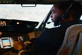
The Learjet 45 is not a large aircraft, and the fuselage cross-section is slightly oval to increase headroom in the cabin, which is 1.5m high. The fuselage is 1.55m wide, so the cockpit is snug, but not cramped. Climbing into and out of the seat is restricted, but not difficult.

Jim Dwyer, chief of flight-test programmes, took the right-hand seat, while flight-test engineer Kirk Vining occupied the jump seat. The seats on this aircraft are not to production standard, but have similar features, such as a five-point harness and adjustable armrests. Rudder-pedal adjustment is electric, controlled by switches on the instrument panel next to each pilot's outboard knee.

The field of view through the windscreen is a delight, generally, because of the lack of pillars, but the downward slope of the upper edge as it sweeps round results in a pronounced cut-off in steeply banked turns. Each pilot can easily see the wingtip on his side. The laminated windscreens are electrically heated for defrosting and demisting, with an outer skin treated to repel rain. Blowing air over the windscreen to remove rain has been found to be unnecessary, so the blower and duct will be deleted.

There is insufficient room in the cockpit for flight bags, but there is document stowage outboard of each seat and a rack for approach-plate books in the bulkhead behind the captain's seat.

There is no overhead panel, and the electrical fuse-panels are located on the cockpit walls outboard of the seats. System controls which might be found overhead in a larger cockpit are arranged in a row along a panel beneath the main instruments. The electrical panel is in front of the captain's right knee and the pressurisation controller in front of the co-pilot's left knee. Although this means leaning across the cockpit to reach a panel in front of the other pilot, important items are positioned towards the cockpit centre, while the anti-ice, lights, landing-gear and hydraulics panels are sited in the centre and readily accessible to either pilot. An exception is the two pilots' radio-communications and navigation-aids selectors and volume controls. These are located outboard on the main instrument panel and cannot be monitored or re-set by the non-operating pilot on behalf of the pilot flying.

All the system-panel switches are push-button selector indicators, as part of the "dark-cockpit" philosophy. Only if a system is not correctly selected, or a malfunction occurs, would the relevant legend illuminate.

The cockpit is dominated by the cathode-ray-tube (CRT) displays of the Honeywell Primus 1000 avionics system. Only four 200 x 170mm CRTs are used, to save space in the relatively small cockpit. Each pilot has a primary-flight display (PFD), presenting attitude and horizontal-situation information, but the second CRT has to be used for both the multi-function display (MFD) and engine-indication and crew-alerting system (EICAS). These can easily be switched from one side of the cockpit to the other, so that, for example, the captain's CRTs display the PFD and EICAS while the first officer's display the PFD and MFD. Viewing the EICAS display at an angle across the cockpit does not seem to cause problems.

Two radio-management units located side by side in the centre of the instrument panel centralise all frequency selections. These flat-panel colour displays are also used as back-ups for the EICAS and MFD. They are small, but adequate for temporary use should one of the four main displays fail.


Digital start-up

More than half the Learjet 45 customers have specified the optional AlliedSignal ER100(LJ) auxiliary power-unit (APU), which is installed in the tailcone and provides bleed air for cabin air-conditioning and electrical power for ground operations - but which is not designed for use in the air. Our aeroplane, N453LJ, did not have an APU.

The Learjet 45 is powered by two Allied-Signal TFE731-20R turbofans. The two-spool, geared-fan engines are flat-rated to 15.5kN (3,500lb) thrust at sea level, up to 32 degreesC. An automatic performance-reserve (APR) increases thrust to 16.2kN if the other engine fails. A digital electronic engine-control (DEEC) system provides thrust management (but not auto-throttle), overspeed and over-temperature protection, engine synchronisation and the APR.

The control panels for engine starting and emergency shutdown, including initiating the fire extinguishers, are on the centre console. Starting is electrical, using a combined starter- generator. The APU can supply power for the starter motor. In its absence, use of a ground-power unit is recommended, although an aircraft-battery start can be made in temperatures above -18 degreesC. Engine starting normally uses an automatic sequence provided by the DEEC, but a manual procedure is available.

On this occasion, engines were started using ground power and the automatic sequence. The relevant power lever was moved from the cut-off detent and placed at idle. The associated start switch was then pushed and the automatic start monitored by the pilot for smooth acceleration, temperature and oil pressure.

The DEEC does not have the authority to abort an automatic start, so, should the process not go correctly, the pilot would have to shut the engine down by lifting a small latch on the power-lever stem and returning it to the cut-off detent. Before engine start, the displays had been switched on (using ground power) and the airfield departure entered for display on the MFD. The transition from GPU to engine-driven generators did not affect the EFIS.

Digital steer-by-wire nosewheel steering is selected by a switch next to the undercarriage lever and controlled through the rudder pedals, via a computer which provides variable steering-authority based on pedal deflection and aircraft groundspeed. Except when demanding full nosewheel deflection, the pedal forces are light and it is easy to over-control, but this tendency is quickly overcome.

Speed control while taxiing would normally be via the Dee Howard target-type thrust reversers, which are hydraulically activated when selected via roll-over levers mounted on the power levers. The thrust reversers are not cleared for use, however, although they have been successfully used during much of the development programme, and they are locked closed until formally certificated. The carbon-disc wheel brakes are smooth and progressive at taxiing speeds, however, and the Learjet 45 is easy and pleasant to taxi.

The parking brake is set by pulling and turning a small red T-handle at the rear of the power-lever box. Pulling the lever slightly operates the emergency-brake system, which is checked while taxiing.

Wichita's Mid Continent Airport is typically vast and taxiing to the holding point afforded plenty of time to brief for the take-off. Pre-take off checks were completed using a paper checklist which includes a table to enable pitch trim to be set in harmony with the flap selected (a checklist can be displayed on the MFD).

Aircraft weight was 8,035kg (maximum take-off weight is 9,160kg); flaps were set at 8 degrees and pitch trim at 5.9 degrees. Field elevation was about 1,400ft (430m), air temperature 26 degreesC, and the resultant reference speeds were V1 (decision speed) 109kt (200km/h), Vr (rotate) 113kt and V2 (climb safety) 126kt.

The displays were arranged throughout the flight so that my left-hand panel was the PFD and my right-hand panel was the EICAS. On the co-pilot's side, Dwyer had the PFD on his right and the MFD on his left. The main portion of the EICAS display is used for engine parameters, while a rectangular box to the right is reserved for crew-advisory messages. Along the lower portion of the screen, fuel quantity, flap position, pitch trim and outside temperature are shown.

For take-off, the power levers are moved forward through the first two detents to the take-off slot. Each detent can be felt, but imposes only a slight restriction to power-lever movement so that some familiarity is needed to select the correct detent by feel. The selected power-lever position is displayed on the upper edge of the EICAS, however, where it can be seen easily. Once take-off power has been selected, the engines spool up rapidly under the command of the DEEC.


Rapid acceleration

Aircraft acceleration was rapid and keeping straight was easy, using nosewheel steering then the rudder as it became aerodynamically effective at about 40kt. Rotation was relaxed, with pleasant control forces ,and the aircraft was established in the climb at about 15 degrees pitch. Undercarriage and flaps were retracted without discernible trim change, and power was reduced to maximum continuous.

Before take-off, the spoiler lever (on the centre console to the left of the power levers) had been set to ARM, the normal selection for take-off and landing. Had the take-off been aborted, the spoilers would deployed automatically once the power levers had been closed to idle, provided groundspeed was more than 60kt.

The plan was to climb to 46,000ft for high-altitude manoeuvring. I wanted to go to the maximum operating altitude of 51,000ft, but was told that the aircraft can reach that level only at light weights, towards the end of a flight. The climb was flown at 250kt at lower level and Mach 0.72 at altitude.

Trim was straightforward, using the typical Learjet "coolie-hat" switch on the outboard grip of each pilot's controlwheel. Moving the switch vertically controls pitch trim via the electrically operated, variable-incidence, tailplane. Moving the switch laterally controls the roll trim via a tab in the left-hand aileron. The rudder-trim control is a small "double-decker" rotary switch on the centre console, which gives directional trim via the rudder trim-tab.

While climbing through 9,500ft at 250kt, with the yaw damper off, a rudder doublet was applied to excite Dutch roll and to note the natural damping. The roll was damped in four cycles. With the yaw damper on, reaction to a rudder doublet was deadbeat. There is only one yaw damper, and the Learjet 45 will be cleared for despatch without the yaw damper for flight at up to 33,000ft. A quick longitudinal-stability check at 15,000ft and 250kt showed the Learjet 45 to be positively stable.

Although the aircraft has pleasantly harmonised control forces in all three axes at airspeeds below about 200kt, at 250kt the pitch forces became higher, while the roll forces remained unchanged. The aircraft has an elevator up/down spring built into the longitudinal control-system to augment pitch stability at cruise speeds by providing higher elevator stick forces with increasing airspeed.

control forces

While higher forces with higher speed are to be expected, I found the increase in longitudinal control force to be more than I had expected. In practice, it is unlikely to be a problem, as the electrical pitch-trimming is quick and effective and pilots will presumably become used to trimming out forces almost subconsciously.

Operating between 44,000ft and 46,000ft over south-west Kansas, 45 degrees banked turns were flown in both directions at M0.75, with no trace of stall buffet. A brief excursion to M0.83 in a shallow descent provoked no Mach buffet. During the subsequent descent through 39,000ft at M0.74, spoilers were fully deployed in their airbrake mode. Extension took about 5s and resulted in little pitch change, but there was discernable aerodynamic burble. With the power levers at idle and airbrakes out, the rate of descent was 7,000ft/min (35.56m/s) at M0.7.

Spoilers can be deployed symmetrically, as airbrakes or to dump lift on the ground, and asymmetrically for roll control - as airbrakes, they will still respond differentially to roll demands. In-flight spoiler extension is proportional to selector-lever position in the "extend" arc of its quadrant. The hydraulically operated and electrically controlled spoilers should not be used as airbrakes when flaps are deployed.

The ailerons are mechanically operated and have a balance tab to reduce roll-control forces. Whenever a controlwheel is turned through more than 5 degrees, the spoilers begin to extend, to augment the ailerons. Blending between the ailerons and spoilers is such that roll demand is seamless. Two steep turns at 60¹ bank and 260kt were flown at 16,000ft, confirming the excellent roll control, but also reinforcing my reservations about the pitch forces at higher airspeeds.

Speed was reduced to look at some low-speed handling at 130kt clean, and 120kt with 8 degrees of flap. As these speeds, the Learjet 45 is pleasant and reassuring, with the control forces in all three axes back in harmony.

Much thought has clearly gone into the Learjet 45's behaviour at or near the stall - witness the vortillons, sawtooth leading edges and stall triggers already mentioned. Then there are the delta fins common to the other Learjets. Introduced mainly for Dutch-roll damping, they were also found to produce a strong nose-down pitching moment at high angles of attack. This characteristic led to stalling behaviour such that a stick pusher was not required.

The first stall was clean, power-off, at 16,000ft. The stick shaker activated at 116kt and the minimum speed seen was 96kt, in fairly heavy buffet. Then, with gear down and full flap (40 degrees), another power-off stall was attempted. Dwyer briefed that both rudder and roll control should be used, to keep the wings level. Stick-shake occurred at 95kt, the right wing dropped and the aircraft rolled to about 60¹ of bank. A minimum speed of 89kt was seen, and roll control remained effective, although application of opposite aileron and rudder to counter the wing drop resulted in rapid roll in the opposite direction, particularly as airspeed began to increase with the nose-down attitude.

The only way to avoid over-controlling seemed to be to neutralise the ailerons and then recover from whatever attitude the aircraft was in as it accelerated. I asked Dwyer to demonstrate a stall in the same configuration, which he did convincingly, but his technique involved a lot of roll and rudder inputs, countering any tendency for the wing to drop with rapid, small and well co-ordinated movements.

Dwyer has stalled the Learjet 45 more than 1,000 times during the development programme, and I concluded that the fully developed stall with gear down and full flap should be approached with caution and a little practice to acquire the correct technique.

There was little pitch-trim change with undercarriage selection, but more with flap selection - the larger the flap angle, the more marked the change - but the Learjet 45 has configuration trim to counter changes in gear, flap and spoiler position. It was inoperative on this particular aircraft, however, so it was not possible to judge its effectiveness.

The Learjet 45 has single-slotted Fowler flaps, which are hydraulically operated and electrically controlled. The flap selector (on the aft right-hand side of the power-lever quadrant) has four positions: up, 8 degrees, 20 degrees and down (40 degrees). There is a gate at the 20 degree position, and the selector has to be pulled out slightly to move it to the down position. The primary flap-position indicator is on the EICAS panel.


Beating jams

The Learjet 45 has been designed to meet the latest control-jam requirements. In the case of an elevator jam, a red T-handle on the centre console, next to the captain's right knee, would be pulled to separate the two control surfaces. The captain's controlwheel is connected by cables to the left elevator and the co-pilot's by another set of cables to the right elevator. In an aileron jam, a small red lever attached to the rear of the captain's controlwheel can be moved to disconnect it from the aileron control circuit (the co-pilot's wheel remains connected). The captain's wheel then provides roll control by sending electrical demands to the spoilers.

Dwyer was keen to demonstrate this capability. I pulled the roll-disconnect lever on my controlwheel, and he imitated jammed ailerons by gripping his wheel with some aileron-defection applied. I was able to control the aircraft comfortably through the spoilers. Artificial friction is introduced at the captain's wheel upon disconnection, to provide some level of feel, but the control forces remain commendably light. The disconnect lever was then returned to its normal position, reconnecting the wheel with the ailerons - a convincing demonstration.

Next on the agenda was an engine shutdown and a V2 climb. The left power-lever was moved to idle then, after about a minute, the latch was lifted and the lever moved to cut-off. The flap was set to 8 degrees (the undercarriage was up) and the V2 climb from 8,500ft started at 126kt ,with APR selected on the right engine.

The aircraft was easy to fly, with a climb rate of about 1,000ft/min and right-rudder foot forces of around 27-32kg, using the recommended technique of 3 degrees wing down towards the live engine. A rudder-boost system operates whenever high-force rudder is applied to maintain directional control, such as when an engine fails on take-off . Yaw-servo torque is provided - whenever pedal force exceeds 23kg - which will override the yaw damper. When the rudder-pedal force is released, the yaw damper will resume operation.

All systems worked as advertised. The fuel system is simple, with two main tanks (one in each wing) and an aft-fuselage tank which gravity-feeds the wing tanks. Airframe anti-icing is straightforward, using bleed air channelled to the wing and tailplane leading edges, and engine nacelles. The hydraulic system has two engine-driven pumps, with a DC pump for the emergency operation of the gear, flaps and brakes.

Next under scrutiny was the Honeywell autopilot, used to fly a coupled instrument-landing-system (ILS) approach to Mid Continent. Although Dwyer warned that there were still software shortcomings, mainly in ILS-centreline capture from large intercept angles, the autopilot performed accurately and well.

The coupled descent from 10,000ft involved a combination of manual power-lever operation and autopilot pitch demands using the controlwheel pitch-trim switch, but without pressing the centre button as required for manual trim. The autopilot flew the localiser and glideslope accurately, while the approach speed was maintained with manual power-lever control.


FLY-ON landing

The recommended landing technique is to close the power lever at about 50ft at the landing reference speed (111kt in this instance) and to "-fly the aircraft on" with the minimum of flare. This technique seemed to work well. The aircraft was pleasant to handle into ground effect and, at touchdown, the trailing-link main gear was notably forgiving.

A touch and go was completed, followed by a visual circuit and full-stop landing. A final take-off was then made, during which Dwyer simulated an engine failure by closing the right power lever at V1. The aircraft continued to accelerate to Vr and was reassuringly easy to rotate, climb and to keep straight on one engine. On both the full-stop landings, automatic spoiler selection and wheel braking (with anti-skid protection) resulted in taxiing speeds without drama despite the absence of reverse thrust.

The Learjet 45 is pleasant to fly, keenly priced and offers an attractive cost of ownership. These qualities should allow it to perpetuate the Learjet charisma into the next century.

Source: Flight International