Time is becoming a critical factor in air traffic control.

Harry Hopkins/BOSCOMBE DOWN

Research and planning for more efficient European air traffic control (ATC) in the next century emphasises the precise use of the fourth dimension: time. The UK Defence Research Agency (DRA) at Boscombe Down, in Wiltshire, has continued studying this since the middle of 1994, when it was awarded a three-year, £4.5 million extension of its UK Civil Aviation Authority contract to investigate the airborne aspects of "4-D" navigation.

It is intended, that enhanced, flow management and future reductions in separation over Europe, will be supported by high navigational accuracy and continuous communication. To this end, installation of Mode-S secondary radar and its two-way datalink should be complete over most of Europe in 1998, with a full datalink service in place by the year 2002.

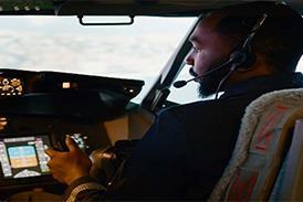
I went to Boscombe Down to test 4-D navigation in the DRA's experimental BAC One-Eleven 200 and was given a taste of things to come in the aircraft's future cockpit. A research electronic flight-instrument system (EFIS) is fitted, while a navigation display (ND) and primary flight display in front of the captain are part of an experimental flight-management system (EFMS) and control-and-display unit (CDU) being developed within the framework of Eurocontrol's Programme for Harmonised Air Traffic Management Research.

With the inertial-navigation system running, we initialised the EFMS, via the liquid crystal CDU mounted on the centre pedestal. This is larger than the CDUs now in commercial use and is covered by a touch-screen. A format such as this can be programmed according to the flight phase.

Because a touch-screen is sensitive to an inadvertent brush of a hand, other EFMS control combinations being considered, include a pressure-sensitive pad, roller-ball cursor-control of the EFIS display and direct voice input.

Aircraft data were keyed into the CDU, while the route was constructed in the EFMS, together with a target-altitude profile, so that a total "trajectory" was calculated.

A plan view of the route was displayed on the ND. Switching it to "profile" allowed the vertical path's cross-section to be shown - from standard instrument departure (SID), up to cruising level and from top of descent (TOD) to destination.

Trajectory-clearance "negotiation" with ATC was carried out through a simulated Mode S datalink. I selected the next line on the CDU (which acts as a "conversational" scratch pad between cockpit and ATC) and our flight plan was transmitted for ATC approval. This was given, confirming both trajectory and timing. Activating the plan confirmed the route in the EFMS and automatically notified activation to ATC.

As a taste of the silent cockpit, the "call" for start-up clearance was input by tapping a guarded "button" area at the top of a second touch-screen suspended from the glare-shield, simulating a VHF datalink. The clearance message was displayed, then accepted with a touch on the legend. The legend then cleared, giving local control an acknowledgement.

I had already "received" the current airfield data on this screen: three pages, each having ten cues for individual airfields to call up Volmet (continuously broadcast weather reports). A printer at the rear of the console prints clearances and weather.

When the engines were running, a second button was touched, and clearance to taxi to runway 23 at Boscombe Down airfield was quickly displayed. The airfield taxiway chart then appeared automatically on the ND, with our position (derived from the differential global-positioning system), shown as a yellow point. The ND reset itself upon receipt of take-off clearance, and we folded away this secondary clearance panel.

After acceleration to a clean configuration take-off, auto pilot engagement also selected automatic thrust. Lateral navigation mode captured the route and vertical navigation was armed, to initiate a route climb profile from 4,000ft (1,250m).

NARROW ROUTE

The white route line is shown on the ND, embraced by parallel yellow lines, set for test purposes at 0.8km (0.5nm) each side. The lines appear upon activation of the flight-plan. Two brackets, ahead and behind, define a time limit "bubble" within the trajectory "tube".

The tube is defined vertically, on the profile display, by similar yellow limit lines about the climb path: 1,000ft above and below for the climb, 200ft in cruise and 500ft in descent. The present-altitude symbol is at the profile bottom during the climb. To make scanning easier, it is central in the cruise, and at the top in descent.

To see the narrow lateral boundaries clearly during the SID, I selected minimum scale on the ND. Full-time display of the limit lines at all points of the route seems unnecessary, however.

The limit lines are variable and will be kept as wide as possible, according to the congestion of local airspace. The minima chosen will be based on type-performance accuracy, experience and airspace available. Each bubble of airspace will have a safety envelope of further un-displayed margins about it. Any position within the displayed bubble is acceptable.

The pilot is now aware of time in seconds, rather than minutes - tens of seconds, anyway. The CDU shows cross-track, altitude, speed and time errors. Seconds of deviation are shown against the aircraft markers, on both the route and profile displays.

Each ND way-point is tagged with name, planned altitude and time to the nearest second. A regular EFIS-type display could become cluttered with navigational aids or airfields and weather overlaid, so this format will be reviewed. A larger-format EFIS, showing data for the next two-way points along the ND top edge, would be easier to read.

In-flight negotiations proposed by ATC are highlighted on the ND. At one point in our flight, the EFMS CDU displayed an altitude constraint - 22,000ft (6,700m), crossing an airway, before we were allowed to continue our climb to 24,000ft. On acknowledgement, by a touch on the CDU, our flight plan was "regenerated" instantly, ready for confirmation. The plan is always regenerated at the start of the cruise, to ensure target times.

Should the requested cruise regime be already near to maximum Mach number or ceiling, compliance will not be possible. The EFMS then responds with a "best-fit" response to an ATC proposal for increased altitude or earlier time.

We then processed a further ATC request, for earlier arrival at our destination. An advance of 45s lifted the indicated airspeed, from 250kt (460km/h) to 275kt on acceptance. Throughout, time error rarely exceeded a couple of seconds, but this will be relaxed to reduce auto- throttle activity.

We had headed into a wind of 330/75kt; the EFMS had to take account of a reversal of wind component as we turned about and the airspeed decreased again. Even with this large change in wind component, the aircraft tracked the curved route as though on rails.

Future ATC will take account of severe route weather and wind variations. Evaluation of the potential of "perfect" forecasts, and automatic downlinks of wind velocity and temperature, is taking place through the UK Meteorological Office. A whole "grid" of data from points over a large area could then be automatically transmitted to the EFMS.

It is important to keep to schedule, right up to the "metering point" - where the flight enters terminal airspace. Here, the flight plan was again regenerated, to establish a more precise TOD.

CONTROLLED DESCENT

The EFMS still controlled our airspeed but, to meet schedule, the descent-path profile is varied by power. With a stronger tailwind than planned, this could not quite be achieved with idle thrust, so when we were 600ft high on datum I edged out a little speed-brake until the auto-throttle levers advanced again.

With higher power - for example, when all de-icing equipment is on - such adjustment might be needed. With a conventional EFIS, having a profile deviation scale and "add-drag" flag, profile monitoring would be less frequent.

The microwave-landing system (MLS) datalink might be used on approach, but at the moment data cannot be received omni-directionally from its transmitter. It is not vital, however, because a high-integrity updated stand-alone EFMS database is already part of a 4-D traffic system.

The transition from EFMS control by air data to joining an MLS profile is progressive and blended.

At 5,000ft, downwind to the north of Boscombe Down, our airspeed reduced to 200kt, as in the EFMS plan, and a 90¡ turn was made at the approach point. From there, an MLS-defined path of two segments took us to join the runway centreline and then capture a 4.5¡ glide-slope. Coupled approaches on a continuous MLS curve are part of the programme.

After the approach gate, the pilot is free to continue to reduce speed and reconfigure the aircraft. ATC will be relying on normal approach routines and closely observed speed schedules.

The auto-pilot held speed and descent slope well in a gusty 25kt cross-wind as our landing clearance was transmitted to us. I disconnected the auto-pilot at 1,000ft, to increase descent rate and recapture a normal 3¡ visual-approach slope. I forgot, however, that this disconnects the auto-throttle too, so 15kt was gained before speed was re-stabilised for flare to a landing in a 15kt cross wind. Once the aircraft was on the ground, the airfield chart re-appeared on the ND and our yellow position dot led us back to the parking area.

If Europe proceeds with a concept like this, not only would the cockpit have evolved further into the electronic age, but, the terminal area controllers will be like the pilot - monitoring only. The accuracy of the trajectory would mean there is little need for radar vectoring and virtually no need for voice exchanges.

Source: Flight International