Assembly of the MDC F-18E/F is meeting or exceeding its performance guarantees.

Graham Warwick/ATLANTA

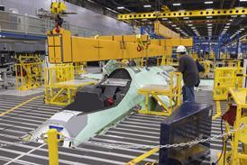
When McDonnell Douglas (MDC) lifted the first F-18E forward-fuselage out of its assembly jig on 12 January, development of the US Navy fighter was on schedule and within budget and the aircraft was a remarkable 550kg under its specified weight.

"The aircraft is meeting or exceeding all of its performance guarantees," says F/A-18E/F vice-president and general manager Jerry Daniels, who adds that the use of "innovative design, fabrication and tooling techniques", has also made assembly easy.

Comments on the aircraft's size are frequent when touring the assembly line at St Louis. The F-18E/F is essentially a scaled-up F-18C/D, with longer fuselage and larger wing and tail. That the resulting aircraft is similar in size to the company's F-15 is becoming apparent as major sections of the first F-18E take shape at St Louis and El Segundo, California, where principal subcontractor Northrop Grumman builds the centre/aft fuselage.

The E/F upgrade will extend the F-18's range, increase its payload and survivability and provide growth capacity to take the aircraft beyond 2020. The upgrade also addresses the F-18's affordability.

MDC was awarded the $4.88 billion contract for F-18E/F engineering and manufacturing development in June 1992. With more than 40% of the development budget spent, it cites as keys to the programme's success:

integrated product development (IPD) - responsibility, authority and accountability for cost, weight and performance of component parts is given to multi-disciplinary teams;

design for manufacture and assembly (DFMA) - a major reduction in parts count has reduced weight, tooling costs and assembly time and improved first-time quality;

low-rate expandable tooling (LRET) - new assembly concepts are being used, to minimise tooling costs and avoid the need to re-invest in tools for production;

manufacturing management plan - a "road map" describes how lean-manufacturing initiatives will be implemented in the transition from development to low-rate initial production.

MORE FOR LESS

Although the E/F is externally similar to the C/D, there is little structural commonality between the aircraft. Although it is 25% larger, the E/F has one-third fewer parts than the C/D - 11,789, compared to 17,210 - thanks to the DFMA concept.

Examples of DFMA include, a "unitised" nose-barrel bulkhead, developed for the E/F and subsequently applied to the C/D. Machined as a single piece from a billet of aluminium, this bulkhead replaces the 90-piece fabricated component originally used in the F-18, for a 3.4kg weight decrease, $3,746 design-to-cost saving and 20-day cycle-time reduction. Eleven assembly tools were eliminated.

DFMA reversed the impact on aircraft weight of larger wing leading-edge extensions (LEX), says IPD group manager engineering Douglas Jaspering. The larger LEX was required to restore manoeuvrability to C/D levels. The C/D LEX is 5.2m2 in area, weigh 172kg and have 950 parts. The E/F LEX covers 5.8m2 weigh 154kg and consist of just 245 parts.

New processes, which make DFMA possible, include high-speed machining (HSM) of aluminium. Very fast, very light, passes with a small-diameter cutter impose virtually no loads on the material, which allows the design of thinner, less rigid, machined parts. HSM has allowed MDC to convert sheet-metal assemblies to machined parts, saving 30kg on 154 E/F parts and reducing tooling costs and cycle time.

MDC's 60,000m2 machine shop is being upgraded with more HSM machines as the company moves to "rate-transparent" machining. Multiple-spindle numerical-control (NC) machines, are ideal for batch production, but, with rates dropping the company wants to be able to produce individual parts on demand, using more-flexible single-spindle machining centres.

Increased use of HSM has generated higher-than-expected demand for NC programming, creating a bottleneck in the production of machined parts, MDC admits. Offsetting this is the high quality of geometry data emerging from the Unigraphics computer-aided-design (CAD) system used by all the E/F partners from the outset of the programme.

A new NC progam is first tested using Veracut simulation software, then loaded on to the target machine for a trial run, using scrap metal or high-density foam. The trial part is inspected for defects before the program is released for production.

The all-important titanium wing carry-through bulkhead, which MDC machines under subcontract to Northrop Grumman, was first cut from aluminium, to check the program. "We have used every one of the E/F titanium bulkheads cut from Day One," says machine-shop superintendent Jim McDonald.

The benefits of the common Unigraphics-based electronic product-definition shared by E/F contractors are becoming apparent as the first aircraft comes together. The first MDC-machined carry-through bulkhead took less than 10min to install in Northrop Grumman's tool, says F-18 programme manufacturing director Kent Beran.

DFMA is also tied to process improvements. MDC machines E/F wing spars from extruded bars, rather than forgings, to minimise warping and has reduced the number of machining steps, cutting the spar cost per aircraft from $13,500 to $9,400, by using the side, as well as bottom, of the cutter.

Process changes, where beneficial, are being inserted into C/D manufacture, to maintain commonality. "If we re-invent a process for the E/F, we read it across to the C/D," says Jaspering, noting that the E/F IPD teams keep responsibility for the equivalent C/D parts.

SIMULATED ASSEMBLY

In a first for aerospace, MDC believes variation-simulation analysis (VSA) is being used to determine how the three-dimensional build-up of tolerances during manufacture, fabrication and assembly affects the final product. The E/F has much tighter mould-line tolerances than those of the C/D, says Beran.

Used by the automotive industry, VSA takes part-geometry data from the CAD database, statistical tolerance data for parts and assemblies, and the assembly sequence, and simulates how the aircraft goes together. This allows tolerances to be varied to achieve a better fit and guides the designer to areas where there is most benefit in adjusting tolerances.

Data from the analysis is then used to drive improvements to processes, to achieve the statistical tolerances required. This results in smaller designed-in gaps and fewer design changes as the aircraft comes together, Jaspering explains.

The E/F assembly concept involves building the aircraft from the inside out, says Beran, to achieve the mould-line tolerances required. The C/D forward-fuselage is built in quarter panels which must be located, spliced and shimmed, he says. This can result in steps of up to 0.75mm between skin panels, which is not acceptable on the E/F.

The move to low-rate expandable tooling has saved 28% on conventional tooling, MDC says. While the high-rate tooling built for the C/D forward fuselage consists of 27 tools, MDC has built just three mainframe tools for E/F forward-fuselage production. These share 18 auxiliary jigs, which are loaded into the mainframe tools as required to locate parts.

The forward fuselage is assembled entirely in the mainframe tool, rather than moving down an assembly line through a series of increasingly complex tools. This "car-wash" approach was first used by MDC on the AH-64 helicopter and is being adopted for T-45 assembly. LRET applications on the F-18E/F include the centre and aft fuselage, wing and vertical tails.

Splicing of the forward and centre/aft fuselage sections of the first F-18E is scheduled for May. This is a complex process on the C/D and MDC will use a Nicholson laser-guided alignment system on the E/F. Fuselage sections will be mounted on fixed tools, with the forward fuselage attached to computer-controlled jacks and slides which allow it to be moved horizontally, vertically and laterally and in roll, pitch and yaw."We will rock the sections until we get the best fit," says Jaspering.

DECEMBER DEBUT

MDC is on schedule to fly the first of seven flight-test aircraft in December. There will also be three ground-test articles. Avionics-integration testing is expected begin in February in MDC's 1,100m2 mission-system test centre in St Louis.

The centre houses more than 40 integrated test stations and allows MDC to assemble and test the complete F-18 avionic system. Integration testing comes after supplier testing and before flight-testing, MDC explains, and is intended to find problems early in the programme, before the cost of correcting faults becomes prohibitive.

The E/F has C/D avionics, with changes essentially limited to cockpit displays and flight-control software. An integration-test station has been installed for the new cockpit, which features Kaiser liquid-crystal displays.

Other preparations for the first flight have included painting of an F-18C, to evaluate manual application of the conductive coatings and tapered surfaces required to meet the E/F's signature requirements, Beran reveals.

Conductive coatings will be applied across all surface-panel joins on the E/F to reduce radar signature.

Robotic painting, is one of the lean-manufacturing technologies, planned for insertion into the E/F programme in the 18- to 24-month gap, between development and low-rate initial production scheduled to begin in 1997.

Source: Flight International